
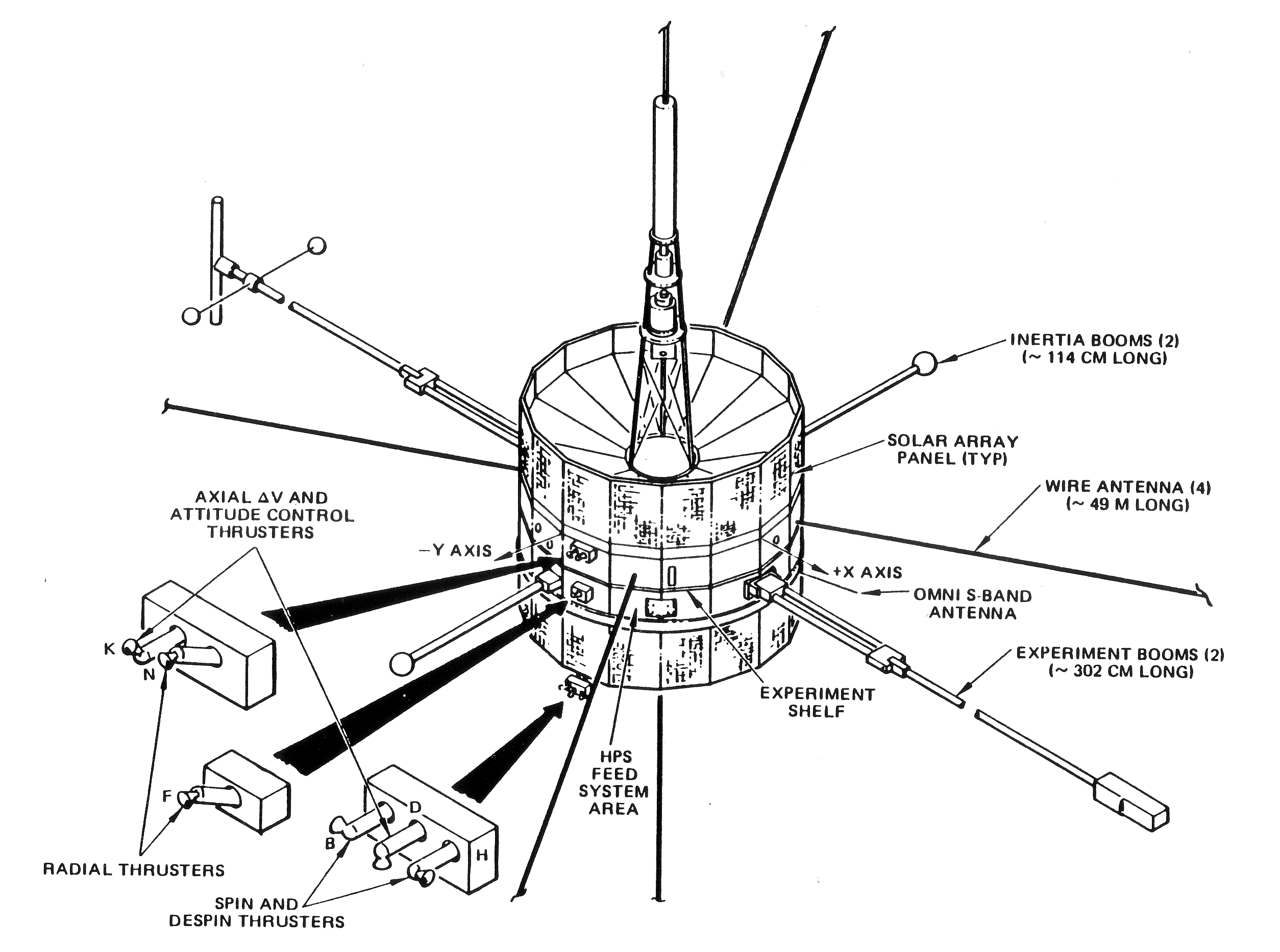
The ISEE-3 spacecraft is a 16-sided drum-shaped structure designed for spin-stabilized operation. [click on image to enlarge] It measures 161 centimeters in height and 174 centimeters in diameter and had a nominal mass of 457 kilograms at launch. The solar array covers the side of the spacecraft except for a band near its center from which various booms and antennas extend.
Mass Properties as of August 1987 (Booms, Wires, and 2-Axis Antenna All Deployed)
– Mass 921.400 lbm
– 2-Axis Moment of 430.85 slug-ft2 Inertia
– Center of Mass (CGz) 19.98 in.
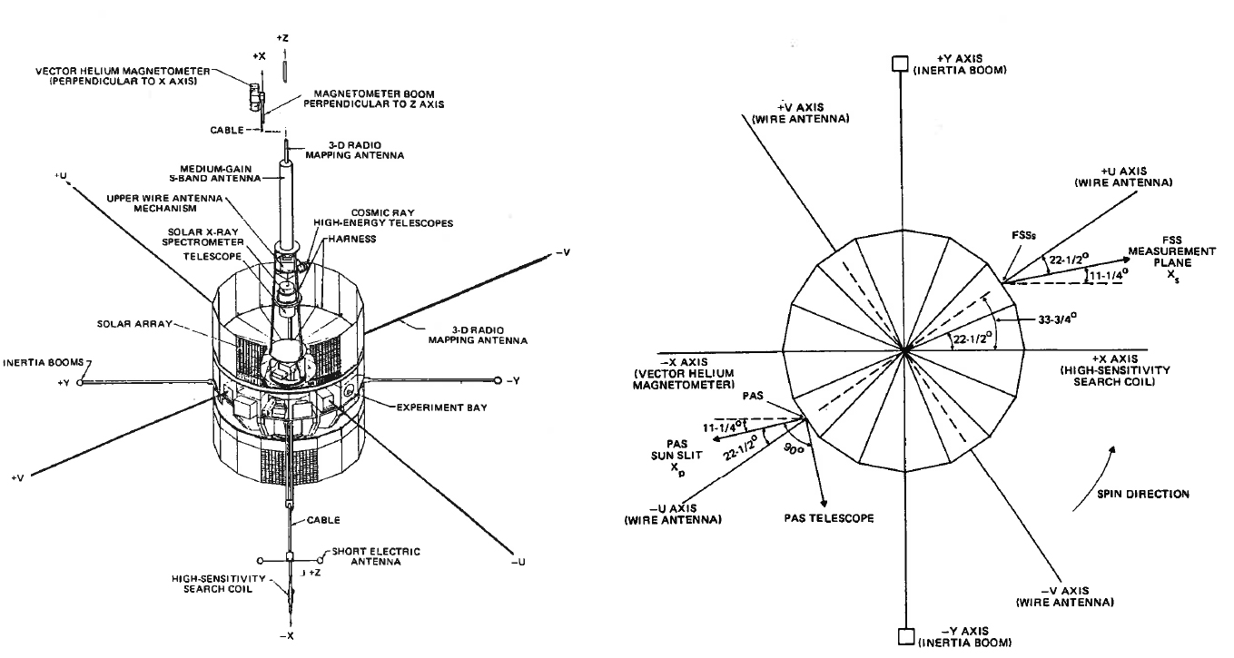
Four rigid booms and four wire antennas extend from the midsection of the spacecraft. The four rigid booms define the X and Y body coordinate axes of the spacecraft. The Z-axis is the spin axis, and the origin of the coordinate system is the separation plane, approximately 32 centimeters above the bottom of the spacecraft. The ± axis experiment booms are nominally 302 centimeters long, while the +Y axis inertia booms are nominally 114 centimeters long. All booms were folded against the spacecraft during launch. The +X axis experiment boom holds a highsensitivity search coil, while the -X axis experiment boom holds a vector helium magnetometer. The four deployable wire antennas extending from the spacecraft midsection are nominally 49 meters in length. These antennas, combined with the deployed ± axis wire antennas (nominal length: 701 centimeters), provide a three-dimensional radio mapping capability.
Eight teardrop-shaped fuel tanks originally loaded with approximately 94 kilograms of hydrazine propellant and 1.3 kilograms of gaseous nitrogen for pressurant are located within the spacecraft. The centers of the spherical portions of the tanks are on a 123-centimeter circle around the Z-axis. A panoramic attitude scanner (PAS) and two fine Sun sensors (FSSs) are located on the sides of the spacecraft.
The ISEE-3 spacecraft carries a fluid-damped accelerometer that is designed and oriented such that thruster thrust levels can be detected during propulsive maneuvers. The accelerometer has a natural frequency of 30 hertz (Hz). The accelerometer is canted 60 degrees with respect to the spacecraft longitudinal axis of symmetry and is nominally aligned in the plane containing the line of action of the radial jets. It is located 19.646 inches above the separation plane (approximately 1.044 inches above the center of gravity at beginning of life (BOL). The accelerometer data are included along with attitude data in the real-time engineering mode telemetry data stream transmitted from the Multisatellite Operations Control Center (MSOCC) during maneuvers.
ATTITUDE AND ORBIT CONTROL SYSTEM (AOCS)
The ISEE-3 AOCS (also called the HPS) is a monopropellant, catalytic, hydrazine, blowdown propulsion system. It provides the capability to perform attitude reorientation maneuvers, spin-rate change maneuvers, and orbit-adjust maneuvers. The AOCS includes the following: 12 nominal 4-pound force thrusters; 8 teardrop-shaped, 18,193-cubiccentimeter propellant tanks; 4 latching solenoid valves; 4 high-capacity propellant line filters; 2 fill-and-vent valves; 2 propellant fill-and-drain valves; and 2 strain gauge-type pressure transducers.
The original fuel budget consisted of 94 kilograms of hydrazine and 1.3 kilograms of gaseous nitrogen for pressurant. The pressurant/prope~llant interface and propellant positioning are maintained by the centrifugal force established by the spacecraft spin.
The AOCS schematic is presented below. Two banks of six thrusters are arranged in a 2-1-3 grouping (refer to the dashed lines in the figure). The propellant tanks are arranged as two, four-tank banks. Magnetically latched isolation valves are electrically commanded to the open or closed position. This allows hydraulic isolation of a bank of four tanks or a bank of six thrusters and feed lines in the event of single-point open failure. The lines and isolation valves are arranged to supply propellant from either bank of tanks to each bank of thrusters by commanding the isolation valves into appropriate positions. [click on image to enlarge]

THRUSTER GEOMETRY
The 12 thrusters include redundant sets of 4 radial thrusters, 4 axial thrusters, and 4 spin-change thrusters. These thrusters are in a coordinate system centered on the separation plane with X and Y axes. This figure shows the overall spacecraft and general locations of one bank of six thrusters. The other bank is located 180 degrees from the bank shown. [click on image to enlarge]
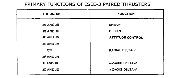
The thruster nozzles are of three varieties: 30-degree angle, 48-degree angle, and 90-degree angle to the thrust chamber axis. These differences are primarily due to aerodynamic heating envelope constraints. The radial thrusters (E, F, M, and N) have 30-degree nozzles. The spin-change thrusters (A, B, G, and H) have 90-degree nozzles. Axial thrusters C and D have 90-degree nozzles, while axial thrusters J and K have 48-degree nozzles. Primary functions of specific paired thrusters are summarized below.
AOCS OPTIONS AND OPERATION
The ICE AOCS provides the flexibility to perform attitude, orbit, and spin-change maneuvers using any combination of the following basic capabilities:
– Number of jets fired: 1 to 12 (in practice, one pair at a time)
– Firing mode: pulsed or continuous (continuous = 360-degree pulse width)
– Pulse width (degrees): 45 or 22.5
– Number of firing sectors: 1024
– Range of consecutive pulses or spin periods of operation: (1 to 63) or (512 to 575)
The ISEE-3 onboard control electronics uses the Sun pulse as a reference for sector generation. Sun-synchronous pulses are generated from th= Sun pulse and the 1024-cycle-per-spin period clock. With this information, the onboard system divides a spin period into 1024 sectors, depicted schematically below.
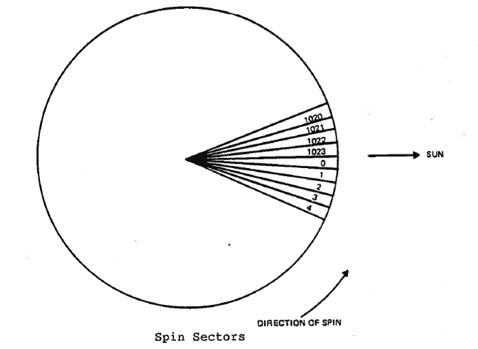
Each command sector equals 0.352 degree of spacecraft rotation regardless of the spacecraft spin rate. The two possible discrete ranges for consecutive pulses/spin periods of operation (1 to 63 and 512 to 575) are dictated by the number of command bits available for specifying the range(s) .
An additional capability unique to radial thrusters M and N is that of being fired in reduced or ratio mode. In essence, the ratio mode provides the capability to fire thruster M or N in the pulsed mode at rates less than one per spin period. Selected thruster M or N can be fired anywhere from 1 per 16 spin periods up to 15 per 16 spin periods, in increments of l pulse per 16 spin periods. This capability can be used operationally to reduce the attitude perturbations resulting from radial AV maneuvers. It should be noted that thrusters M and Ncan only be driven in a pulsed mode, while the remaining 10 thrusters may be fired in the continuous as well as pulsed mode. The various firing ratio patterns are shown below [click on image to enlarge].

The design of the ISEE-3 AOCS electronics provides two separate, identical packages, either of which is capable of providing full control requirements. The packages provide standby redundancy in that only one will be operational with the redundant unit unpowered.
To initiate/terminate AOCS operation, one serial command and four pulse commands are required (in addition to commands to open/close latch valves). The serial command specifies the AOCS options selected for the maneuver, and the pulse commands are used to initiate and terminate the firing sequence defined by the serial command.
The terminate command can be used to interrupt a serial command sequence before normal completion. An uncertainty of one or two pulses (or spin periods) as to when the serial command sequence was actually terminated will result.
Source: Original ISEE-3 NASA program documentation.